")
")

X-ray computer tomography (CT) allows to create 3D-images of the inner structure of objects without opening them. The principle is, to X-ray the object in different directions to get more information about the distribution of the absorption contrast than with radiography. Either the sample is rotated between the X-ray source and the detector or (mostly in medical applications) the source-detector unit rotates around the sample. The X-ray projection in one direction is the so called Radon-transformed of the sample. From the entity of all these projections in different directions, each slice image can be calculated by Fourier-transformation. A 3D-image can then be calculated from a stack of many slice images.
Computer tomography has been developed since 1957 by the groups of Allan M. Cormack and Godfrey Hounsfield and still is subjected to continuous improvement. Some steps in the technical development of CTs are illustrated below.
|
Translation / rotation scanner CT In the first generation systems one X-ray source and one detector are shifted synchronously perpendicular to the axis of rotation to take the data of one projection direction. Then source and detector are rotated a few degrees before shifting them for the data acquisition of the next projection direction. For the next image, the patient is shifted along the rotation axis. In the second generation systems up to ten sources and detectors increased data acquisition speed. Fig. 1: First generation CT-system |
 |
|
|
Rotation / rotation scanner CT In the third generation systems one X-ray source and a ring segment detector array at the opposite side of the patient rotate synchronously around the patient to acquire the image data. In more recent systems the detector is a 2D-array taking up to hundreds of image slices in one rotation ("multislice", fig. 2). The patient is shifted along the rotation axis to get the whole information about the investigated volume. A modern variant is the Helix-CT, where the patient is shifted with constant speed. 2007 these systems provided up to 320 image slices per second or a 12 frames per second live-video of an entire heart. Since 2005 systems using two source-detector units with different photon energies are available. These systems can resolve different tissues more precisely. Fig. 2: Third generation CT-system with two sources and two detector arrays
|
 |
|
|
Rotation / stationary scanner CT In the fourth generation systems the X-ray source rotates around the patient. The detector is a stationary ring shaped array.
Fig. 3: Fourth generation CT-system |
 |
|
|
Electron beam scanner CT (EBCT) In the fifth generation systems the X-ray source consists of a ring shaped target anode and several electron beams (marked green in fig. 4) directed to the target points, where X-rays are generated. The detector is a stationary ring shaped array. The advantage of this system is the absence of moving parts. The disadvantage is the necessity of a large vacuum tube and electron beam steering systems. Fig. 4: Fifth generation CT-system |
 |
|
A large number of CTs is used for medical applications with the capability to scan and image volumes as large as the human body with a maximum resolution of about three points per millimeter (i.e. 75 dpi or about 2000 million voxel (=volumetric pixel) for a 75 kg person). Figure 5 shows a picture of a real CT system and the quality of images taken with such systems. In micro-CT, the spacial resolution is (in 2013) in the range of 1/1000 to 1/2000 of the sample diametre and it reaches a few hundred nanometres.


Fig. 5: Clinical computer tomograph (left) and CT-image (right  ) ©02
) ©02
The image below shows a computer tomography 3D-reconstruction of 17 slices of a human head. Dark areas mark bone, grey areas tissue and white areas antras or air.

Fig. 6: Compter tomographic 3D-image of a human head
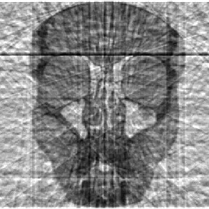
How is a CT image extracted from the detected X-ray absorption? Figure 7 shows the absorption detected on the CCD-detector array when a slice of the head from figure 6 is X-rayed. Observe the dark line in the upper part of the detected CCD-signal. In the actual horizontal direction of the X-rays the optical path through the bones above the eye-sockets is very long and so most of the X-rays are absorbed in these bones, resulting in the dark line on the detector!

Fig. 7: Absorption signal detected when a slice of a head is X-rayed ( in this example the source only passes through a quarter circle).
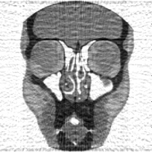
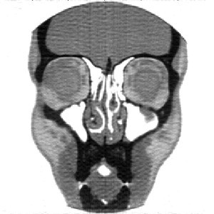
The CT-image can be calculated from the absorption signals detected with the CCD-line array while the source and the detector circle around the head by a so called back projection. To do so, the intensity of the detected signals are projected back from the detector to the source and overlayed in the area of the X-rayed object. In figure 8 a) the back projection from the 90° and from the 0° signal have been overlayed. The horizontal dark line in the upper part of figure 8 a) is again resulting from the absorption by the bones above the eye-sockets. The resulting image has nearly nothing in common with a CT image of a human head. But if the same procedure is carried out with the absorption signals detected in four different directions (figure 8 b)) or even 16 directions (figure 8 c)), some similarities becomes visible. A real CT-image (figure 8 g)) consists of signals taken under hundreds of angles and is thus much more detailed.
 |
 |
||
|
a) CT back projection of the 0° and the 90° signal |
b) CT back projection with four angles |
||
|
|
|
||
 |
 |
||
|
c) CT back projection with 16 angles |
d) CT back projection with 30 angles |
||
|
|
|
||
 |
 |
||
|
e) CT back projection with 90 angles |
f) CT back projection with 180 angles |
||
|
|
|
||
|
|
|||
|
g) CT back projection with hundreds of angles |

Fig. 8: Reconstruction of a CT image of a slice of a human head by back projection.